
- Due to continuous improvement, specifications are subject to change without prior notice,
- Plasticizing capacity is based on the standard test conditions performed by SUPERMAC MACHINERY
- Injection mass, injection ratio and plasticizing capacity differ depending on the resin used & molding condition.
- Kindly contact us to discuss using machine at the maximum capacity.
SMH 2P - Servo
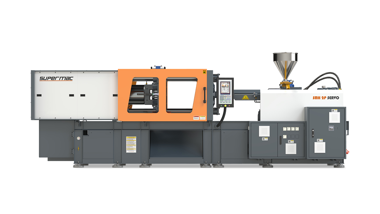
SMH 2P – Servo
Specification
| INJECTION UNIT SPECIFICATION | UNIT | HYDROLINE 2P 350 | |||||
|---|---|---|---|---|---|---|---|
| FRAME A | FRAME B | ||||||
| A | B | C | A | B | C | ||
| SCREW DIAMETER | mm | 60 | 70 | 80 | 70 | 80 | 90 |
| INJECTION PRESSURE MAX | bar | 2262 | 1662 | 1372 | 2263 | 1733 | 1468 |
| MAX. INJECTION WEIGHT (GPPS) | gm | 890 | 1122 | 1583 | 1385 | 1809 | 2289 |
| PLASTICIZING CAPACITY | gm/sec | 33 | 51 | 70 | 42 | 57 | 74 |
| INJECTION RATE | cc/sec | 291 | 396 | 517 | 398 | 520 | 658 |
| INJECTION SCREW STROKE | mm | 350 | 350 | 350 | 400 | 400 | 400 |
| SCREW L/D RATIO | L/D | 23 | 20 | 18 | 23 | 20 | 18 |
| SCREW SPEED MAX | rpm | 180 | 180 | 180 | 177 | 177 | 177 |
| HEATER CAPACITY | kw | 22 | 22 | 22 | 36 | 36 | 36 |
| NO. OF HEATING ZONES | nos | 4+1 | 4+1 | 4+1 | 4+1 | 4+1 | 4+1 |
| CLAMP UNIT SPECIFICATION | |||||||
| MOULD CLAMPING FORCE | tons | 350 | |||||
| MINIMUM MOULD HEIGHT | mm | 300 | |||||
| MAXIMUM MOULD OPENING STROKE | mm | 1100 | |||||
| MAXIMUM MOULD DAYLIGHT | mm | 1400 | |||||
| DISTANCE BETWEEN TIE ROD (H × V) | mm | 760 × 760 | |||||
| MOULD PLATEN SIZE (H × V) | mm | 1130 × 1130 | |||||
| TIE ROD DIA | mm | 120 | |||||
| EJECTOR FORCE | tons | 7.5 | |||||
| EJECTOR STROKE | mm | 200 | |||||
| GENERAL DATA | |||||||
| SERVO MOTOR | KW (HP) | 45 | 45 + 15 | ||||
| OIL TANK CAPACITY | ltrs | 1250 | 1400 | ||||
| WATER REQUIREMENT (inlet temp.29°C) | lpm | 100 | 100 | ||||
| CONNECTED LOAD | Kw | 67 | 96 | ||||
| MACHINE WEIGHT | tons | ||||||
| MACHINE DIMENSIONS (L × W × H) | Ft | 27 × 6 × 7.5 | 28 × 7.5 × 7.5 | ||||
| MODEL | UNIT | HYDROLINE 2P 450 | |||||
|---|---|---|---|---|---|---|---|
| FRAME A | FRAME B | ||||||
| A | B | C | A | B | C | ||
| INJECTION UNIT SPECIFICATION | |||||||
| SCREW DIAMETER | mm | 60 | 70 | 80 | 70 | 80 | 90 |
| INJECTION PRESSURE MAX | bar | 2262 | 1662 | 1372 | 2263 | 1733 | 1468 |
| MAX. INJECTION WEIGHT (GPPS) | gm | 890 | 1122 | 1583 | 1385 | 1809 | 2289 |
| PLASTICIZING CAPACITY | gm/sec | 33 | 51 | 70 | 42 | 57 | 74 |
| INJECTION RATE | cc/sec | 291 | 396 | 517 | 398 | 520 | 658 |
| INJECTION SCREW STROKE | mm | 350 | 400 | ||||
| SCREW L/D RATIO | L/D | 23 | 20 | 18 | 23 | 20 | 18 |
| SCREW SPEED MAX | rpm | 180 | 177 | ||||
| HEATER CAPACITY | kw | 22 | 36 | ||||
| NO. OF HEATING ZONES | nos | 4+1 | 4+1 | ||||
| CLAMP UNIT SPECIFICATION | |||||||
| MOULD CLAMPING FORCE | tons | 450 | |||||
| MINIMUM MOULD HEIGHT | mm | 400 | |||||
| MAXIMUM MOULD OPENING STROKE | mm | 1100 | |||||
| MAXIMUM MOULD DAYLIGHT | mm | 1500 | |||||
| DISTANCE BETWEEN TIE ROD (H × V) | mm | 830 × 830 | |||||
| MOULD PLATEN SIZE (H × V) | mm | 1270 × 1270 | |||||
| TIE ROD DIA | mm | 140 | |||||
| EJECTOR FORCE | tons | 11.5 | |||||
| EJECTOR STROKE | mm | 200 | |||||
| GENERAL DATA | |||||||
| SERVO MOTOR | kw (HP) | 45 + 15 | 45 + 15 | ||||
| OIL TANK CAPACITY | ltrs | 1400 | 1400 | ||||
| WATER REQUIREMENT (inlet temp. 29°C) | lpm | 100 | 100 | ||||
| CONNECTED LOAD | kw | 67 | 96 | ||||
| MACHINE WEIGHT | tons | ||||||
| MACHINE DIMENSIONS (L × W × H) | ft | 29 × 7.5 × 7.5 | 30 × 7.5 × 7.5 | ||||
| MODEL | UNIT | HYDROLINE 2P 650 | |||||
|---|---|---|---|---|---|---|---|
| FRAME A | FRAME B | ||||||
| A | B | C | A | B | C | ||
| INJECTION UNIT SPECIFICATION | |||||||
| SCREW DIAMETER | mm | 70 | 80 | 90 | 90 | 100 | 110 |
| INJECTION PRESSURE MAX | bar | 2263 | 1733 | 1468 | 2132 | 1733 | 1432 |
| MAX. INJECTION WEIGHT (GPPS) | gm | 1385 | 1809 | 2289 | 2632 | 3250 | 3932 |
| PLASTICIZING CAPACITY | gm/sec | 42 | 57 | 74 | 77 | 95 | 128 |
| INJECTION RATE | cc/sec | 398 | 520 | 658 | 612 | 755 | 914 |
| INJECTION SCREW STROKE | mm | 400 | 460 | ||||
| SCREW L/D RATIO | L/D | 23 | 20 | 18 | 22 | 20 | 18 |
| SCREW SPEED MAX | rpm | 177 | 150 | ||||
| HEATER CAPACITY | kw | 36 | 48 | ||||
| NO. OF HEATING ZONES | nos | 4+1 | 5+1 | ||||
| CLAMP UNIT SPECIFICATION | |||||||
| MOULD CLAMPING FORCE | tons | 650 | |||||
| MINIMUM MOULD HEIGHT | mm | 500 | |||||
| MAXIMUM MOULD OPENING STROKE | mm | 1350 | |||||
| MAXIMUM MOULD DAYLIGHT | mm | 1850 | |||||
| DISTANCE BETWEEN TIE ROD (H × V) | mm | 950 × 950 | |||||
| MOULD PLATEN SIZE (H × V) | mm | 1400 × 1400 | |||||
| TIE ROD DIA | mm | 170 | |||||
| EJECTOR FORCE | tons | 12 | |||||
| EJECTOR STROKE | mm | 200 | |||||
| GENERAL DATA | |||||||
| SERVO MOTOR | kw (HP) | 65 | 65 | ||||
| OIL TANK CAPACITY | ltrs | 2000 | 2000 | ||||
| WATER REQUIREMENT (inlet temp. 29°C) | lpm | 125 | 125 | ||||
| CONNECTED LOAD | kw | ||||||
| MACHINE DIMENSIONS (L × W × H) | ft | 32 × 7.7 × 8.5 | 32 × 7.7 × 8.5 | ||||
Standard Features
Clamp
- Large prefill designed for fast tonnage build up
- Hollow headless ram with mono seal & no piston rings
- Unique prefill design for fast tonnage build-up
- High speed traverse cylinders
- T-slot platens with tapped holes
- Adjustable moving platen skates
- Rigid casting platens
- Adjustable 5 stage closing and 5 stage opening speed & pressure
- Adjustable 2 stage mold safety pressure & 1 stage speed
- Position based ramping for switching-precise speed & pressure control
- Linear position transducer for precise clamp position control
- Sensitive mold protection with try again circuit
- Stage wise actual time display
- Insert molding programe
- Actual tonnage read pressure transducer
- Actual tonnage display on screen
Hydraulics
- Servo motor driven pump
- Convenient hydraulic layout for easy approach
- Valves placed near actuators for quick response
- Low oil level indicator
- Continuous oil filtration with 10 micron filter
- Oil temperature on screen
Available Options
- Proportional speed control for mold open & close
- Proportional back pressure control on screen
- Air ejection
- Hydraulic core pull
- Feed throat temperature control
- Part drop sensor for single cavity
- Water manifolds
- Robot interface (EUROMAP 67)
- Extra heating zones
- T-slot platens (110-450 ton)
- Extended daylight with ram spacer
- Eject retract limit switch verification
- Bimetallic barrel & hardened/coated screw
- Ejector on fly
- Free programmable cores
Controls
- Automatic sequence either by codes or free programmable sequence
- 10.5" TFT color display with alpha-numeric keypad
- Actual movement speed & pressure graph display
- 100 mold data storage
- Configurable multilevel password with operator's name
- Graphical hourly production table
- Customized setup menu
- High/low limit display for each adjustable parameter
- 10 diagnose on visualization-analog & digital
- Free I/O assignment
- Change log menu: logs last 100 set points changes with time & date
- Integrated statistical process control (SPC)
- Freely programmable smart outputs
- Over view screen with graphical display of machines functions
- Soft keys for fast access of select menus
- Visual & audible alarm
- Alarm history with date & time log
- Graphical representation of automatic cycle
- Recipe exchange via USB
- Host-PC connection through ethernet
- Remote via modem or internet
- Batch counter with option to turn off the motor
- Mold data/process data/change log saving to external USB device
- Online help
- Function keys with LEDs indicator
Enjector
- Multipoint ejection for uniform force distribution
- Ejector speed & pressure adjustable on screen
- Linear transducer for ejector position
- Pilot operated check valve for ejector
- Multiple pulsating ejector strokes
- Intermediate retract set point
- Ejector stay forward & forward delay timer
Temperature Control
- Meters current display of heating zone
- Heater failure & thermocouple failure detection
- Accurate PID temperature control settable on screen
- Feed throat temperature indication
- Auto heat startup & shutdown
- Heat standby after set number of cycles
- Soak timer for cold start protection
- High/low temperature alarm
- Set & actual temperature data with graph
- Insulated heaters band
- Oil temperature on screen
IN Jection
- Multi stage injection speed & pressure profile
- Multi stage screw speed & manual back pressure control
- Digital setting of screw rpm & digital read out of actual
- Wide choice of injection units with A-B-C screw/barrel combinations
- Comfortable injection unit swivelling
- Switch over from fill to pack based on position or time
- Linear position transducer for accurate injection position
- Injection decompression before/after refilling or both
- Semi-auto purge, cold slung removal & intrusion molding
- Chequered plate below purge area
- Injection start, suck-back & melt decompression-delay timer
- Graphically adjustable alarm bands for injection pressure
- Sliding hopper
- Nozzle contact force by pressure switch